555 Timer Ic Schematic Diagram / Basic Electronic Project Ldr Circuit Using 555 Timer Ic : A collection of 555 circuits using the 555 timer as an astable oscillator with different duty cycles.
555 Timer Ic Schematic Diagram / Basic Electronic Project Ldr Circuit Using 555 Timer Ic : A collection of 555 circuits using the 555 timer as an astable oscillator with different duty cycles.. 555 timer helpers schematic the addition of a capacitor to the trigger will not work for short output pulses as there The 555 timer ic is used as a precision timing device that acts as a timer to generate single pulses or long delays. Check out the huge collection of 555 timer based circuits here. 555 timer pwm generator circuit diagram and explanation: As discussed in the above section, the ic is in its standard monostable mode.
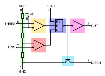
555 timer is an industrial standard ic existing from early days of ic. In short, the 555 timer chip works by detecting threshold voltage levels. In this category, we have handpicked some really useful 555 timer circuits which will be interesting to electronics engineering students and hobbyists alike. 555 ic timer block diagram 555 ic timer block diagram. We have used a variable resistor in place of fixed resistor for changing.
555 Timer Ic Wikipedia from upload.wikimedia.org The 555 timer ic is a very cheap, popular and useful precision timing device which can act as either a simple timer to generate single pulses or long time delays, or as a relaxation oscillator producing a string of stabilised waveforms of varying duty cycles from 50 to 100%. Each mode of operation indicates a circuit diagram and its output. This integrated circuit can be used in a variety of ways from which the basic one is to produce accurate and stable delays in electronic circuits.additionally, it is available in 8 pin dip and 14 pin dip. The block diagram of a 555 timer is shown in the above figure. Derivatives provide two or four timing circuits in one package.it was commercialized in 1972 by signetics. Adjustable on off timer(using 555 astable mode) in this circuit a timer with cyclic on off operations is designed. And, pin 6 detects a voltage above 2/3 of the supply voltage to turn the ic off. 555 timer bistable example circuit.
The block diagram of a 555 timer is shown in the above figure.
That is, monostable, bistable, astable multivibrator. This circuit uses very basic components like 555 timer and 4017 counter. The standard 555 timer ic is made of 2 diodes. Simple 555 timer circuits & projects. 555 timer pin diagram and descriptions. The 555 ic timer circuit above shows a very straightforward design where the ic 555 forms the central controlling part of the circuit. This integrated circuit can be used in a variety of ways from which the basic one is to produce accurate and stable delays in electronic circuits.additionally, it is available in 8 pin dip and 14 pin dip. Derivatives provide two or four timing circuits in one package.it was commercialized in 1972 by signetics. Basic 555 monostable multivibrator circuit. This pin has no special function what so ever. Let us discuss in detail about this circuit. Working modes of 555 timer ic. Internal circuit diagram of 555 ic.
In this pwm generater circuit, as we mentioned above we have used 555 timer ic for generating pwm signal. 555 timers are very popular in electronics. As we know 555 timer ic is one of the commonly used ic among students and hobbyists. 555 timer bistable example circuit. Here we have controlled the output frequency of the pwm signal by selecting resistor rv1 and capacitor c1.
555 Timer Astable Multivibrator Circuit Diagram from circuitdigest.com 555 timer pin diagram and descriptions. The 555 ic timer circuit above shows a very straightforward design where the ic 555 forms the central controlling part of the circuit. Adjustable on off timer(using 555 astable mode) in this circuit a timer with cyclic on off operations is designed. Daman shah june 5, 2021. 555 timer bistable example circuit. As discussed in the above section, the ic is in its standard monostable mode. Look at the block diagram again. In short, the 555 timer chip works by detecting threshold voltage levels.
Working modes of 555 timer ic.
Working modes of 555 timer ic. It is connected to ground as usual. The 555 timer is a simple integrated circuit that can be used to make many different electronic circuits. 555 timer bistable example circuit. Although the schematic looks correct, this basic circuit may actually have a few negative aspects. In 2017, it was said over a billion 555 timers are produced. The standard 555 timer ic is made of 2 diodes. Or separate the on and off switch for a machine. Resistive network consists of three equal resistors and acts as a voltage divider. Referring to the timing diagram in figure 3, a low voltage pulse applied to the trigger input (pin 2) causes the output voltage at pin 3 to go from low to high. Here you have separate on and off buttons to control an led. 555 timer, as the name specified, are the electronics circuits used for measuring time intervals.in this article, we will cover about 555 timers. Now as shown in figure, there are eight pins for a 555 timer ic namely, 1.ground.
And, pin 6 detects a voltage above 2/3 of the supply voltage to turn the ic off. Referring to the timing diagram in figure 3, a low voltage pulse applied to the trigger input (pin 2) causes the output voltage at pin 3 to go from low to high. Being an integral part of electronics project, 555 timer ic is very often used in simple to complex electronics projects. Pin diagram of 555 ic. We have a large collection of simple and advanced projects using 555 timer ic.
The General 555 Timer Circuit Schematic At The Heart Of The Circuit Is Download Scientific Diagram from www.researchgate.net Internal circuit diagram of 555 ic. This integrated circuit can be used in a variety of ways from which the basic one is to produce accurate and stable delays in electronic circuits.additionally, it is available in 8 pin dip and 14 pin dip. 8.power or vcc pin 1. The 555 timer ic is a very cheap, popular and useful precision timing device which can act as either a simple timer to generate single pulses or long time delays, or as a relaxation oscillator producing a string of stabilised waveforms of varying duty cycles from 50 to 100%. The 4rth circuit diagram shows the standard ic 555 adjustable timer circuit having two sets of timing ranges and an output relay for toggling the desired load. As we know 555 timer ic is one of the commonly used ic among students and hobbyists. 555 timers are very popular in electronics. We have used a variable resistor in place of fixed resistor for changing.
The values of r1 and c1 determine how long the output will remain high.
Now as shown in figure, there are eight pins for a 555 timer ic namely, 1.ground. 555 datasheet 555 duty cycle 555 metronome 555 reset function 555 time delay relay inverted 555 timer pulse generator. We have seen in the last few tutorials that the 555 timer can be configured with externally connected components as multivibrators, oscillators and timers, with timing intervals ranging from a few microseconds to many hours. 555 timer pwm generator circuit diagram and explanation: Or separate the on and off switch for a machine. Daman shah june 5, 2021. Here, we take a look at some 555 timer circuits based on the ic. As we know 555 timer ic is one of the commonly used ic among students and hobbyists. Basic 555 monostable multivibrator circuit. There are simple circuits for beginners and advanced engineers. Resistive network consists of three equal resistors and acts as a voltage divider. Being an integral part of electronics project, 555 timer ic is very often used in simple to complex electronics projects. Although the schematic looks correct, this basic circuit may actually have a few negative aspects.
Here, we take a look at some 555 timer circuits based on the ic 555 timer schematic. Each mode of operation indicates a circuit diagram and its output.


Posting Komentar
0 Komentar